Making a Thermostat Smart
I want smart heating. I rent a flat so adapted what was there.
Smart Thermostat
I’ve always liked the idea of a smart heating system - the dream sold by Nest and Hive that you crank up the boiler on your journey home to have the place warm on return. Unfortunately, these systems are quite expensive and involved to integrate, so I decided to stick a motor on the dial on the existing thermostat and go from there.
The feature list:
- Accurately set temperature
- Accessible remotely via the home server (and Google assistant)
- Display showing current setting on the device
- Physical buttons for changing the temperature manually (as if it were a typical thermostat)
Thermostat Assembly
The flat I rent has a heating system installed and to my advantage, the thermostat is wireless. It’s a Honeywell Y6630D, powered by a couple of AAs and was screwed to a hallway wall. I first tried to intercept the RF signal and clone that with a transmitter, however some research found it transmits on an 868MHz frequency…and this is just a really difficult range to find receivers for and apparently Honeywell use some complex two-way dialog with the receiver at the boiler, making it difficult to spoof.
So I settled on going a bit more…analogue.
Here is the original thermostat with and without its plastic cover:
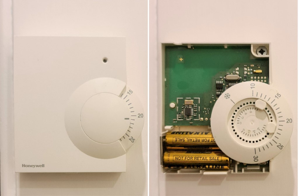
This photo was primarily taken so I could put it back together at end of tenancy
I figured that a simple microservo (servos are basically geared motors - this kind takes an input between 0 and 255 and maps this to a position between 0° and 180°) like an MG90 or SG90 would easily handle the torque needed to spin the dial, and with a 180° degree range, that would be plenty for the temperatures I needed. The current draw is also low enough that I could run it off the same standard USB supply as the microcontroller, without the need for an external supply.
Some hot glue, wood offcuts and 10 minutes later and the whole thing was pretty much built.
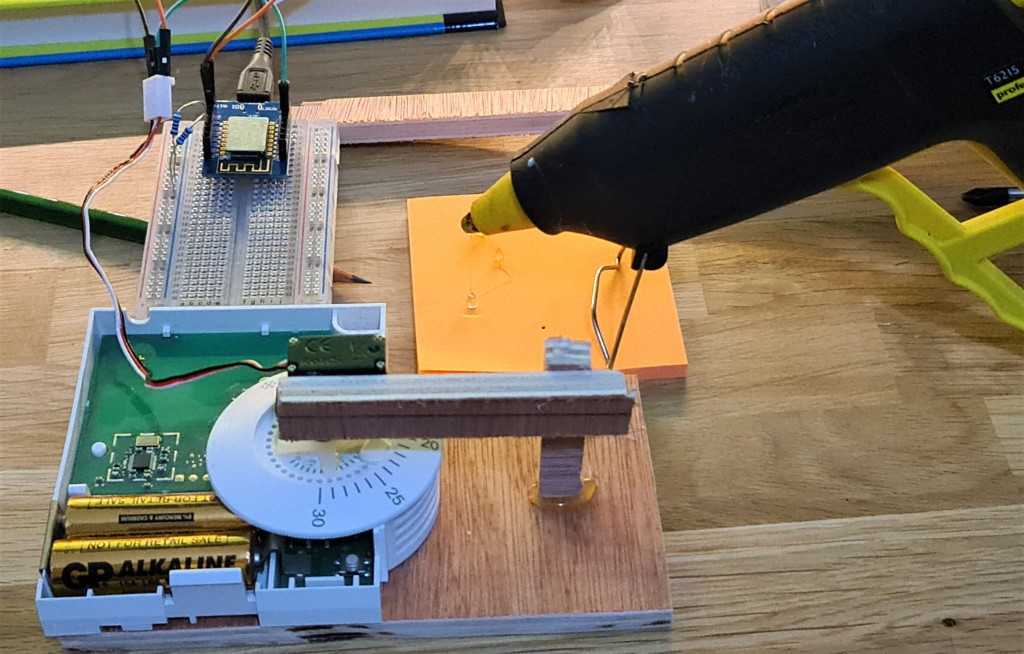
I added some code to send pre-determined servo positions via the dashboard UI in Node Red (the system underlying my entire home automation system) and tests were successful when sending signals from a phone.
*Click to see*
This is just sending the raw servo values to the ESP8266, incrementally moving the motor:
This is after converting the raw servo values to the specific temperatures on the thermostat dial, so the temperatures can be used instead of absolute motor values:
Wiring
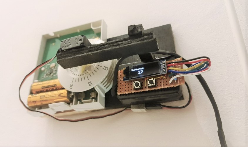
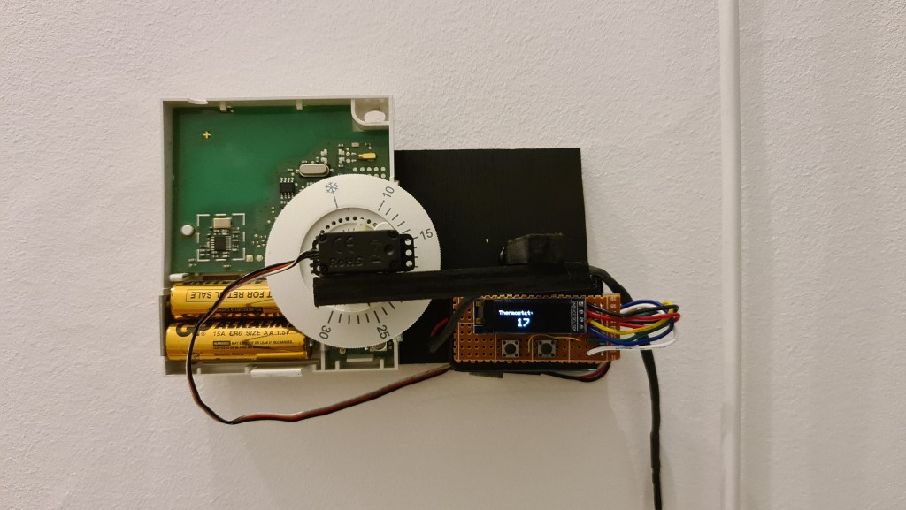
After testing, I soldered an OLED, 2 buttons and the ESP8266 (basically an Arduino with Wifi - the brains of the thing) to some perf board as small as possible so I could fold it into a neater formfactor within a small enclosure I had (the same as those used in the smart energy meter project).
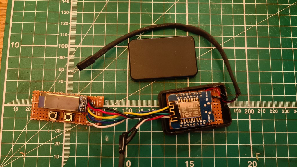
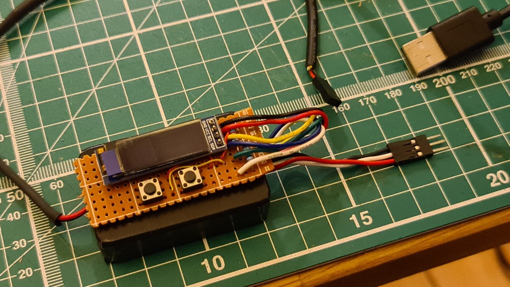
I made a cable to connect the servo separately, so that parts could be swapped out without soldering it all together permanently (cable making was the same as described in the Retro TV project).
The wiring plan looks like this:
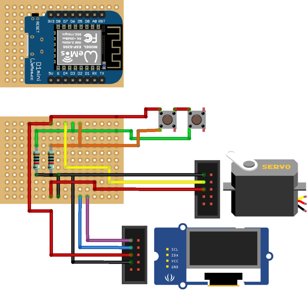
The ESP8266 is shown as a separate board here, but it is soldered on top of the wiring beneath it
I sprayed the wooden parts black, thinking that would somehow make it look neater, and that was it. Mounted back on the wall.
*Click to see GIFs in action*
A quick note on powering servos with arduinos/microcontrollers
This is a theory I have around why an ESP8266 in ideal for small servos, over an Arduino like the Uno:
So if you take something like an Arduino Uno and hook up a servo to its 5V, GRND and a digital pin, you should have a really easy motorised system, right? Well you’d almost certainly have something called servo jitter and may not have enough current for the motor. The Arduino series typically have a voltage regulator feeding the 5V pin (even if you’re powering it off a 5V USB supply), so there’s a maximum current draw of 40mA, which is super low for motor.
However, the great thing about using an ESP8266 in a board like the Wemos D1 (or NodeMCU, or similar clone) is that the 5V pin is coming directly from the USB power supply. This means that if you have a 5V 2A supply (standard phone charger), you pull the ~150mA needed to power the board itself, leaving a huge 1.85A available through the 5V pin. This means you can power motors, LED strips, etc. all with just the single power supply.
Code
The code is here.
The code is fairly straightforward. It takes the required servo position as an MQTT message sent from the home server and just passes it onto the analog line that controls the motor. It took a little reverse engineering to work out the conversion factor of temperature to servo increments (it was about 7.9 per °C) but this calculation is done on the server side, so the ESP8266 just deals with passing the servo position on.
The other bit of fiddling was to get accurate motor positions when moving in several small increments. The servo has a little play in the bearings and if you change from something like 17° to 17.5° and then back down, the motor loses some accuracy. So I implemented a sort of ‘reset’ every time the motor is moved whereby it jumps to 25°C (an arbitrary value I’ll never heat to) before settling. So if you send it 16°C, it’ll hop to 25°C and then jump back to 16°C. This seems to lead to accurate settings every time.
*You can see this 'reset' movement in this clip*
The callback code (the message receiving code on the ESP) takes the servo value and sends it to the motor, and then converts the value back in to temperature (the 48/9+15 part) to display on the OLED:
void callback(char* topic, byte* payload, unsigned int length) {
  messageTemp = "";
  //get the message, write to messageTemp char array
  for (int i = 0; i < length; i++) {
    messageTemp += (char)payload[i];
  }

  //send value to servo if in range
  if (messageTemp.toInt() > 0 && messageTemp.toInt() < 181){
   myservo.write(messageTemp.toInt());
  }
  //convert back to temperature
  temp_c = messageTemp.toInt();
  temp_c = (temp_c-48)/9+15;
  //function to print strings on the OLED
  print2screen(String(temp_c));
}
There’s also the standard Adafruit library for running the OLED which gets the current temperature from the server, and there are buttons wired in a debounced to manually change temperature on the thermostat itself. As the ESP8266 is enclosed, adding the OTA code for Over-the-Air updates was also necessary for any future code changes.
The Node-Red implementation also has NORA running, so it appears as a thermostat in Google Home and can be adjusted from there too.
Along with the previous addition of automating the Eufy vacuum and the Silvia coffee machine, I’m slowly moving forward with automation of non-smart appliances…