Building a Functional 1950s Retro TV
TVs are ugly. They used to be less so. Enter: Retro TV Build
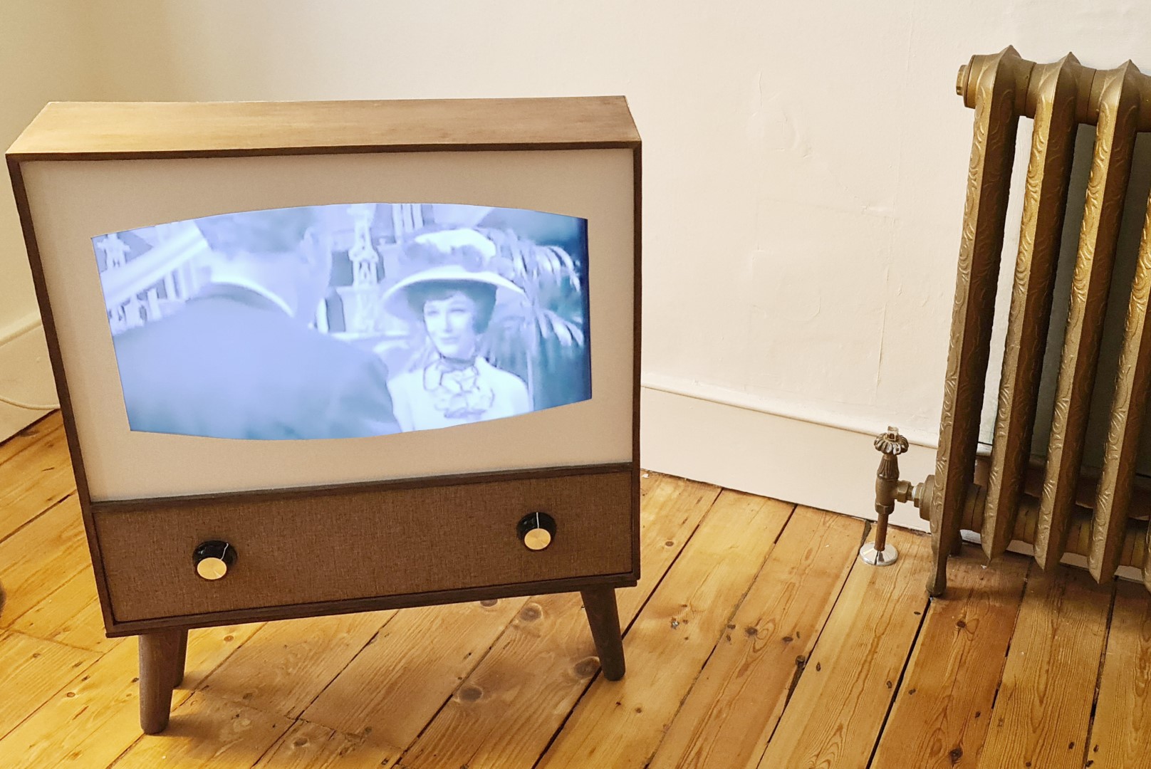
At some point between the advent of plastics and the consumer-availability of televisions (circa 1950s), there was a union of woodwork, textiles and electronics to create pieces to look at home in buyers’ houses. I wanted a small TV for the kitchen/dining room, so decided to ‘skin’ one with some basic wood panelling and a few extras.
Planning
The design started in SketchUp and this guided the wood requirements and cut list.
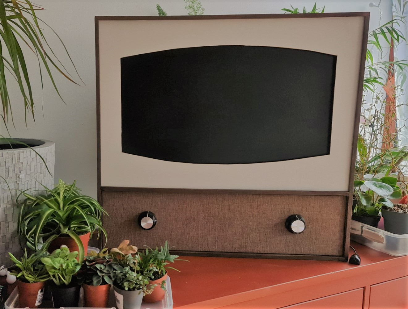
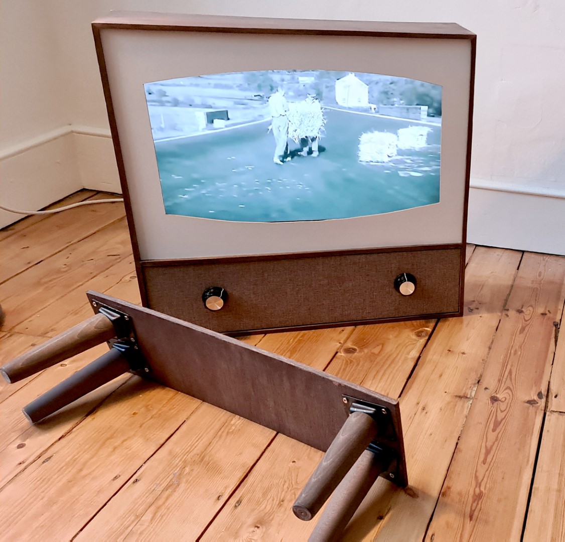
The aim was for something like this:
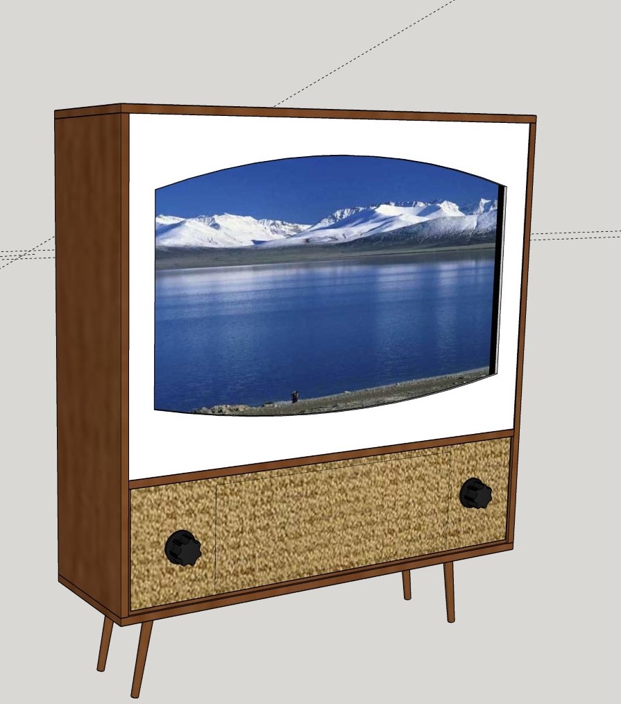
A Google Image search of 1950s television sets provided inspiration and I settled for a speaker panel with knobs underneath the screen, and a white border that would frame the screen with the classic rounded edges (CRT manufacturing required the TV to be a glass ‘tube’ of some kind - so no sharp rectangles).
A ‘blow-up’ of the required parts:
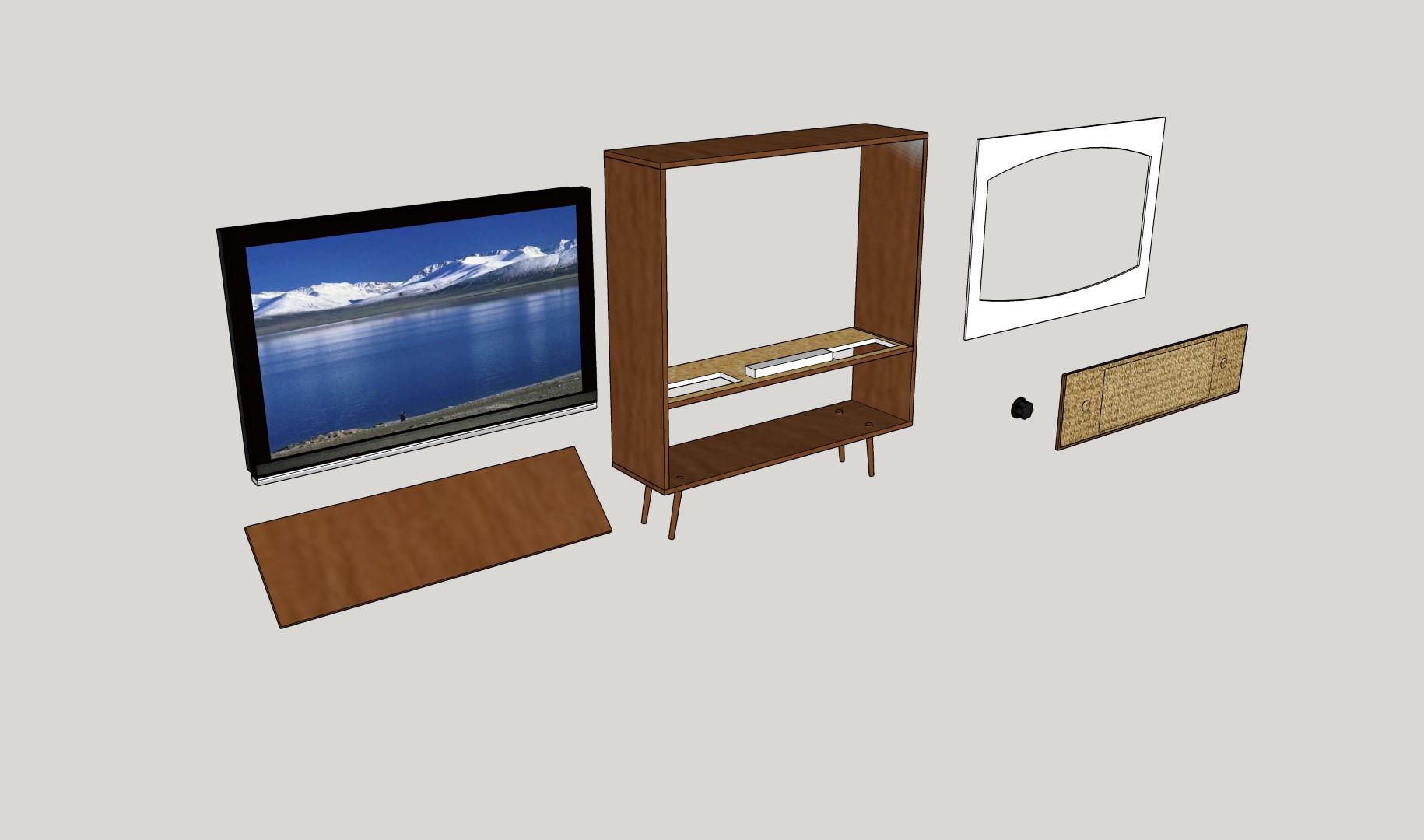
For the most part, 9mm hardwood plywood was used - strong, cheap and easy to work with. For the white bezel, 3mm white hardboard was good as it already has a smooth, white finish. White acrylic was considered, but it would be a nightmare to cut the curves smoothly. For the speaker section, some burlap material from eBay was first tried, but this was too loosely woven so a brown linen weave for upholstery was used instead.
Build
Frame
The side panels were first cut with a jigsaw and the ends bevel cut at 45º, the same process used to build the [smart mirror]([https://optimalprimate.github.io/projects/2020/10/01/smart-mirror.html] casing.
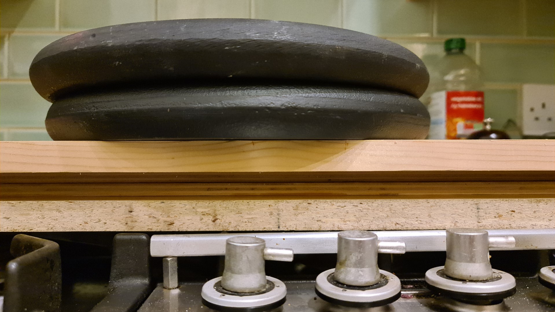
As the plywood was quite warped/bowed, a light spray of water on the concave side and a press down for an hour was needed to flatten the boards out.
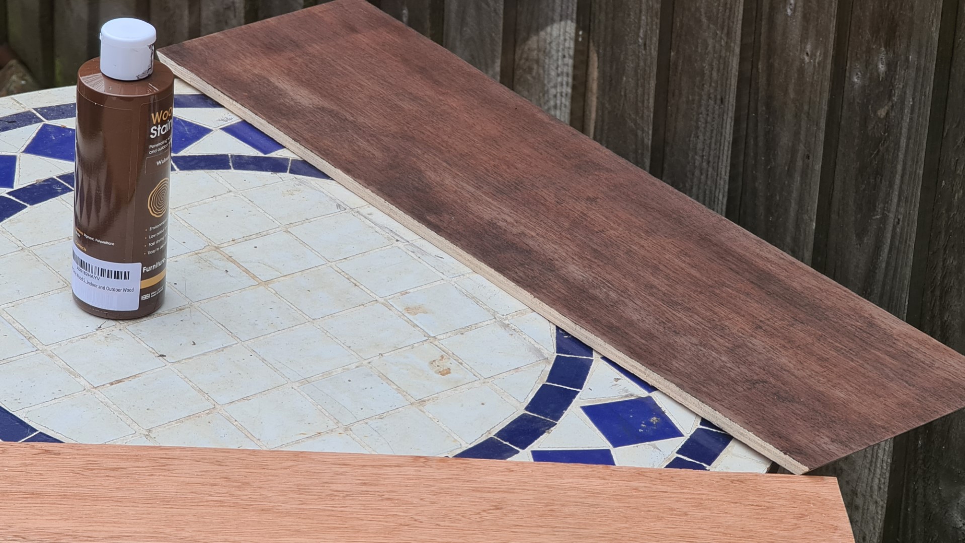
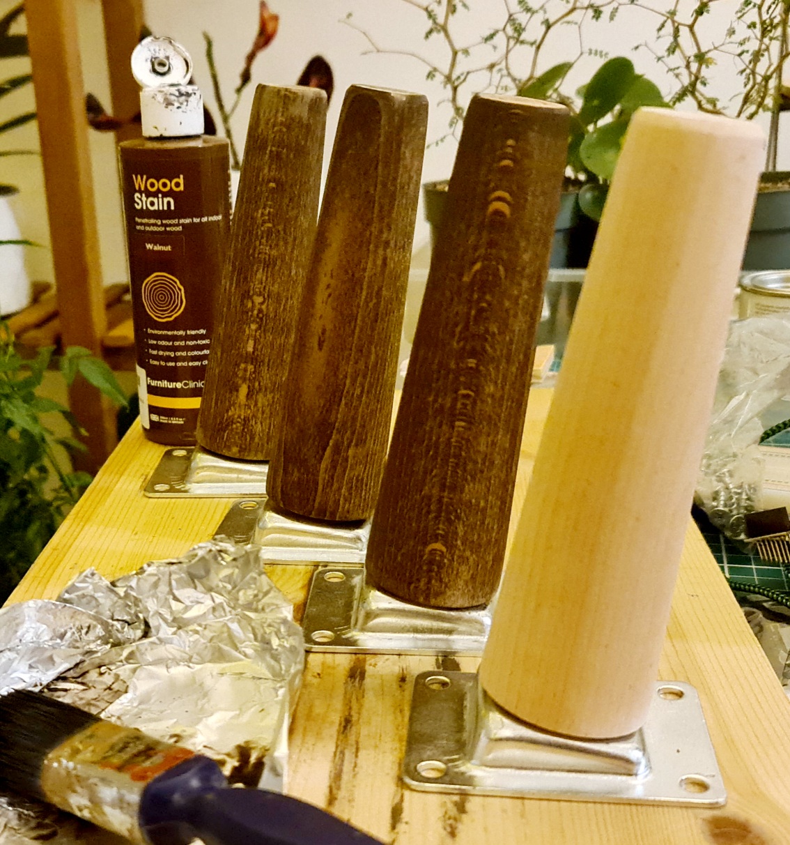
These were then stained with a shade of ‘walnut’ water-based stain, which goes on easily and dries within minutes ready for the second coat. The only issue being that water stains raise the grain of the wood as they soak in, so some sanding required after the first coat. As they’re also less durable, a layer of oil/wax is needed later down the line for sealing.
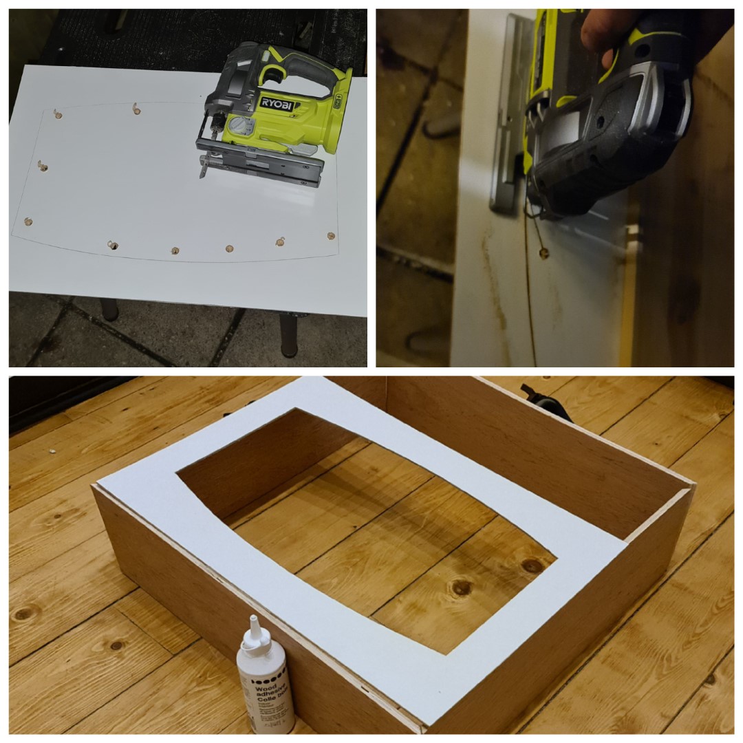
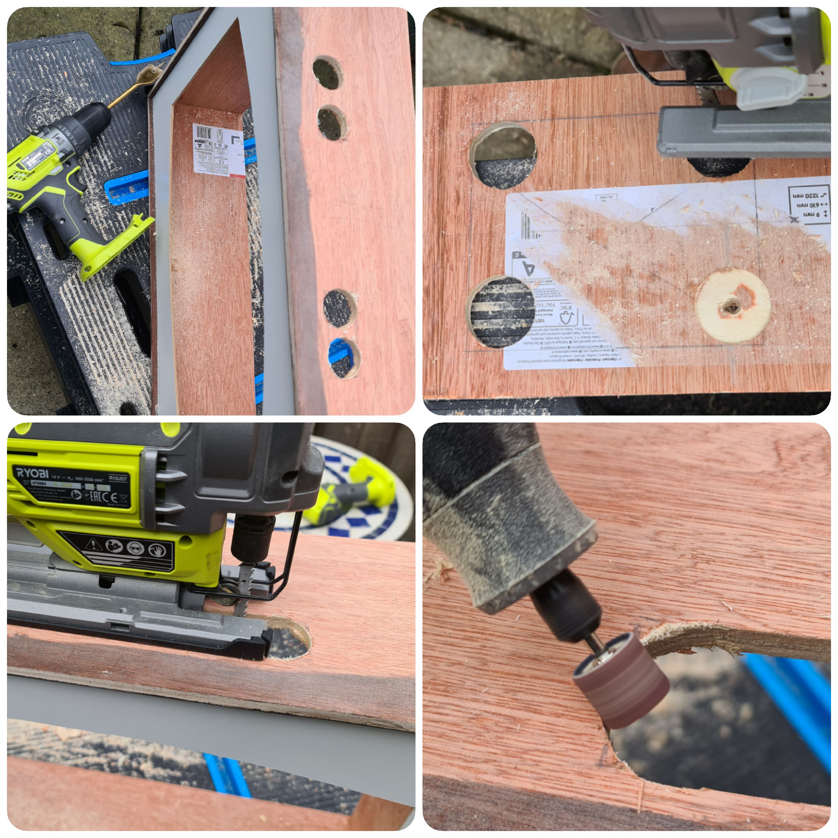
For the white curved border, an elliptical shape was measured out on the hardboard and with a series of 10mm drilled holes, the jigsaw blade ‘joined the dots’ to remove the cutout.
A dremel with a routing bit was used to carve out a fairly rough groove along the insides of the frame into which the hardboard cutout would slide.
Shelf
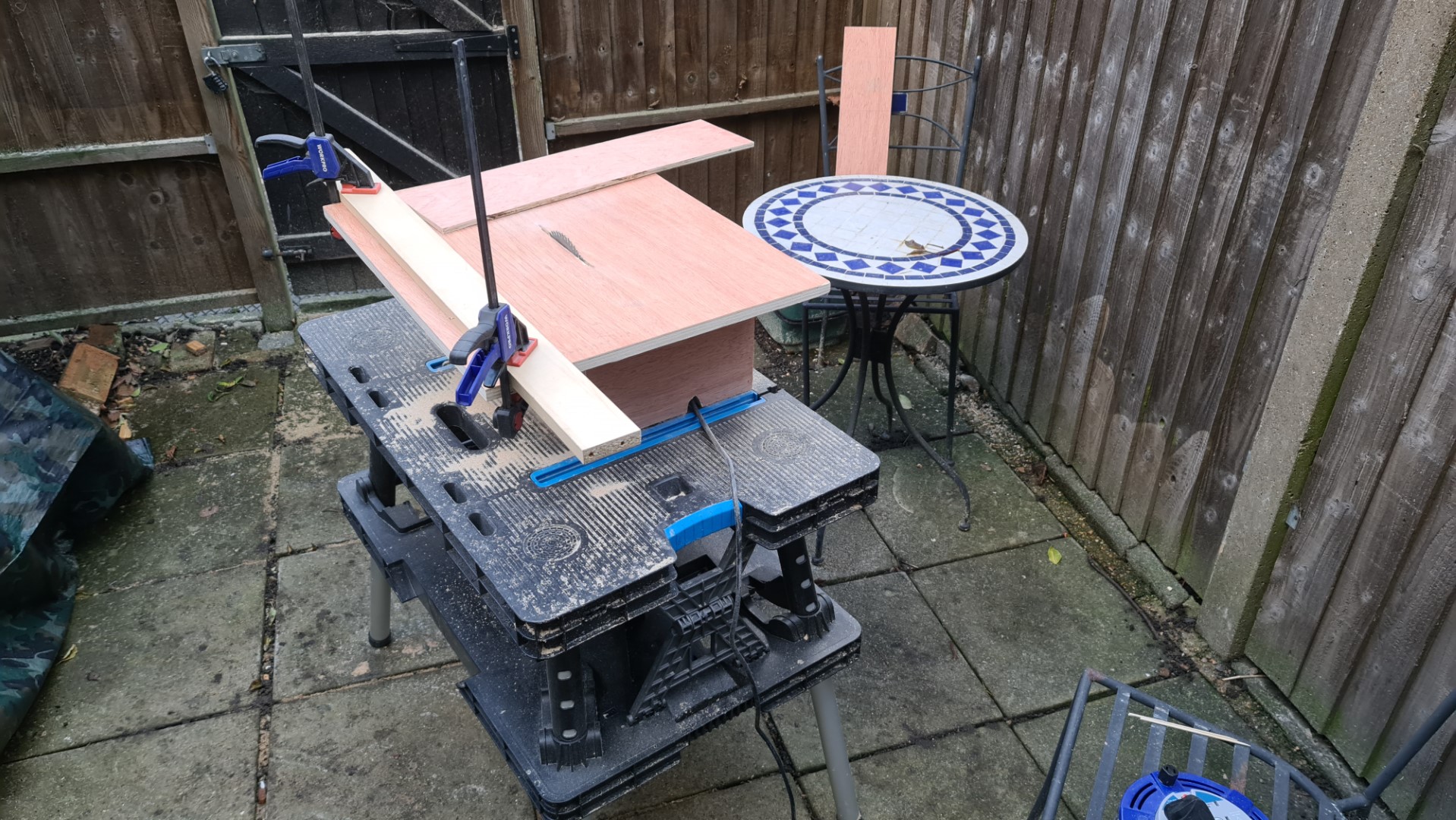
A shelf layer was needed that would sit under and support the TV, and make space for the speaker grille below, so that was another panel cut to the internal width of the frame. It seemed more time-effective to go and build a table saw at this point, so 2 hours, a £35 circular saw and a panel of 1.8mm plywood later, the shelf was cutout in seconds with a straighter edge than the jigsaw could reliably achieve.
This shelf needed holes in it to permit sound to travel from the base of the TV (where its built in speakers exited) and into the space below, as well as holes for cabling to reach the TV. This was achieved with a 16mm spade bit on the drill and again, jigsaw cutouts.
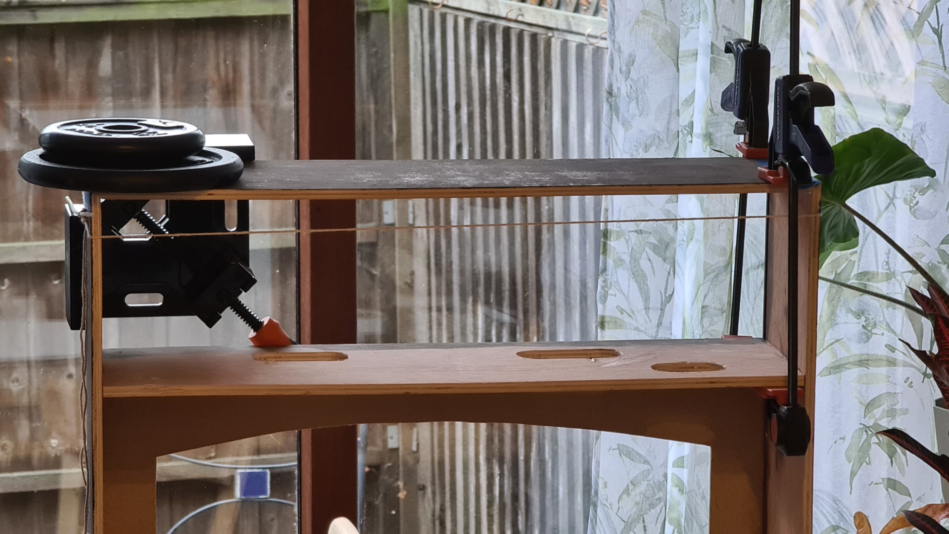
This was then all glued into place with clamps, squares and weight plates. The wood is still pretty bowed, but too late to deal with that now.
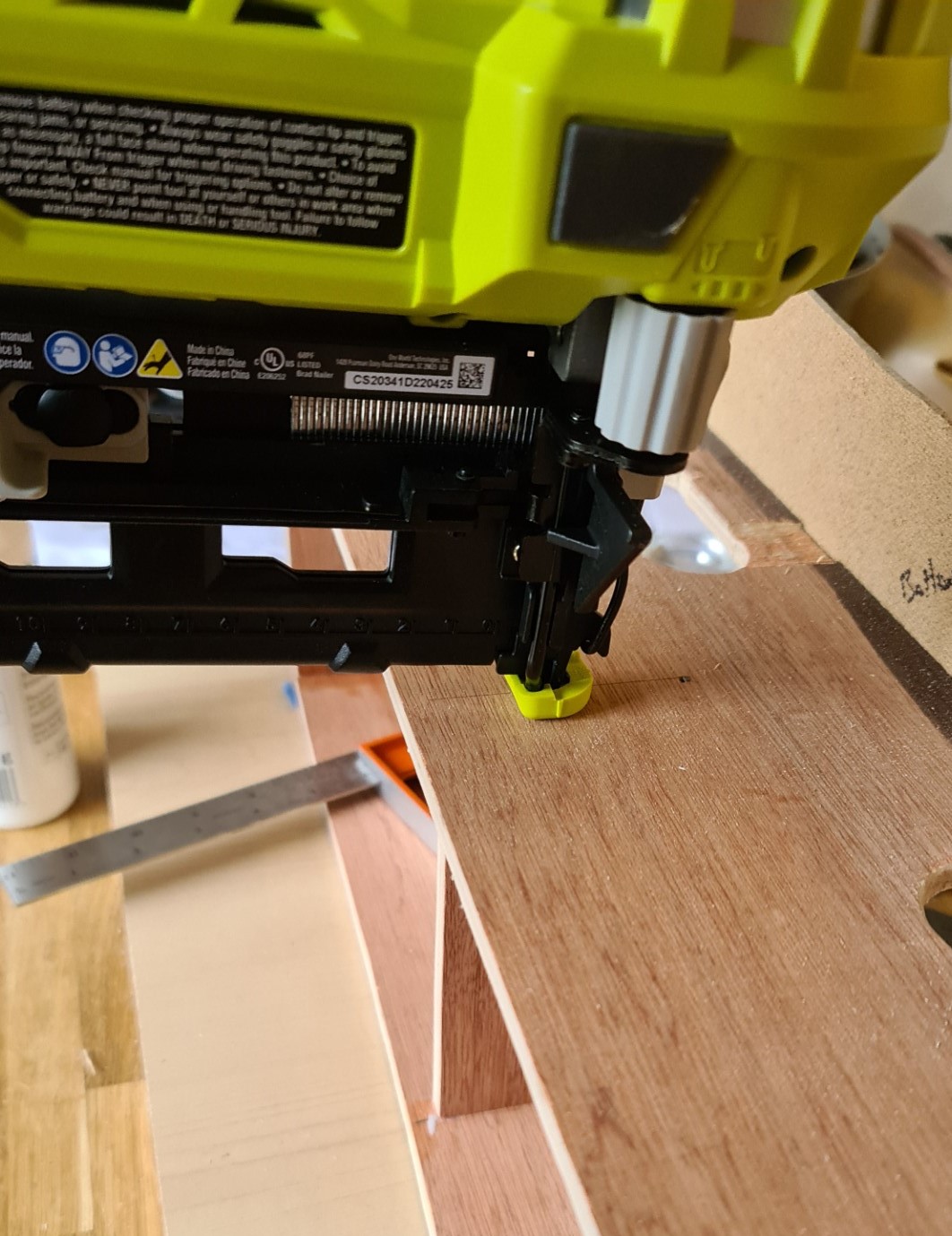
To further support the shelf with the weight of the TV and to attach the speaker front panel, a central support was glued in and, since the joins are internal, could be nailed so progress could continue without drying time.
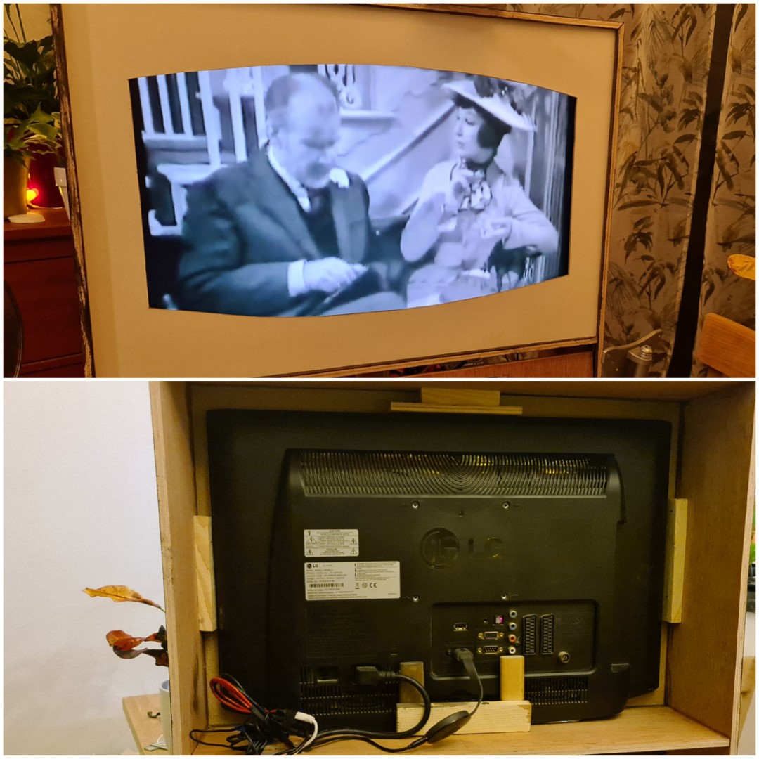
The TV could then be placed inside, with a few scrap pieces of wood to hold it in place. This also allowed testing with a 1950s TV YouTube sample streamed over the Chromecast.
Speaker Panel
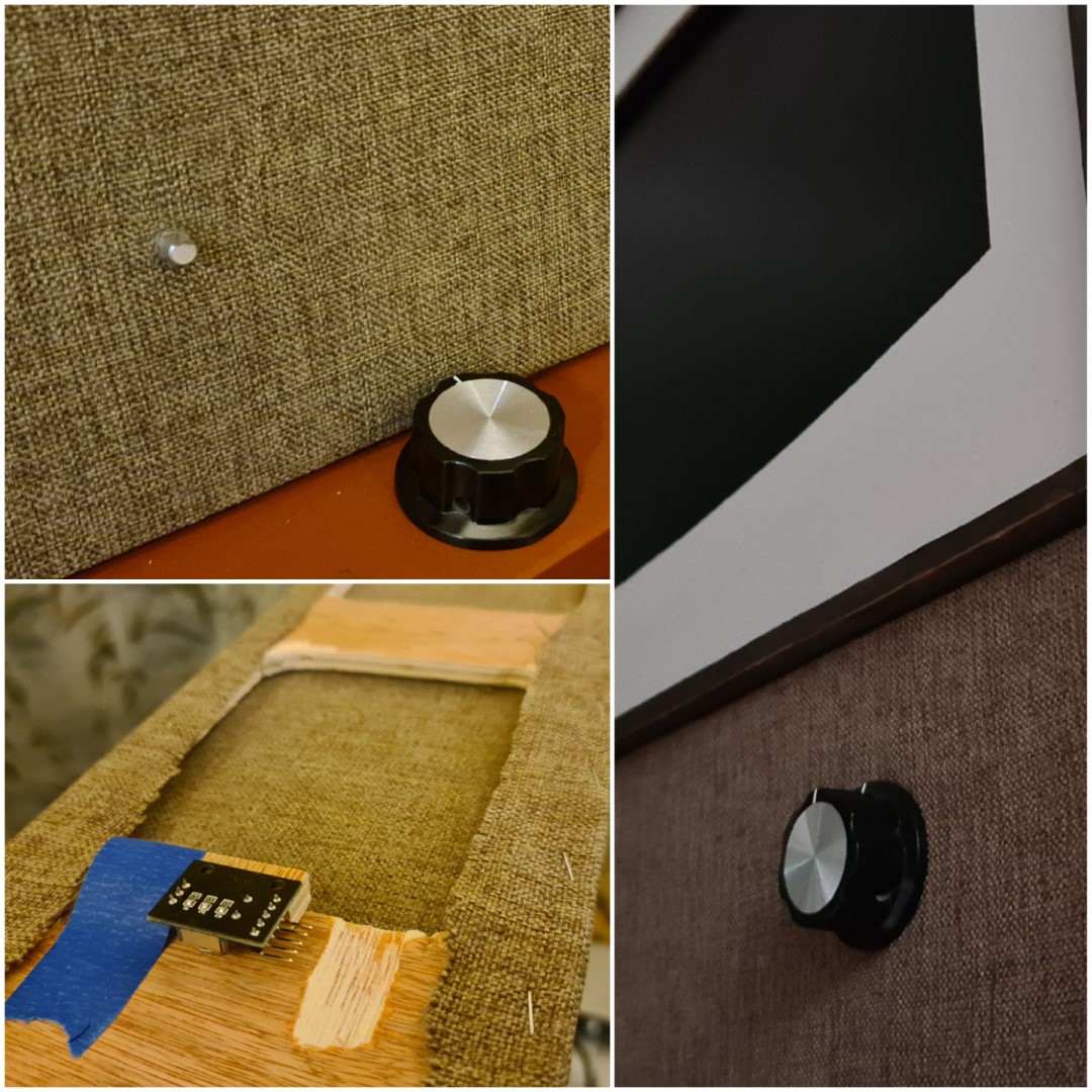
The speaker panel was cut to fit the space below the TV, with two large rectangular holes for sound, with small holes drilled for the rotary encoders to push through for volume and power controls. The upholstery material could then be stapled taught. Finally, the rotary encoders were glued into place with their shafts emerging through the front where the knobs screwed in place.
To finish the edges of the frame, iron-on edging was first stained and then applied to give a clean finish.
Legs
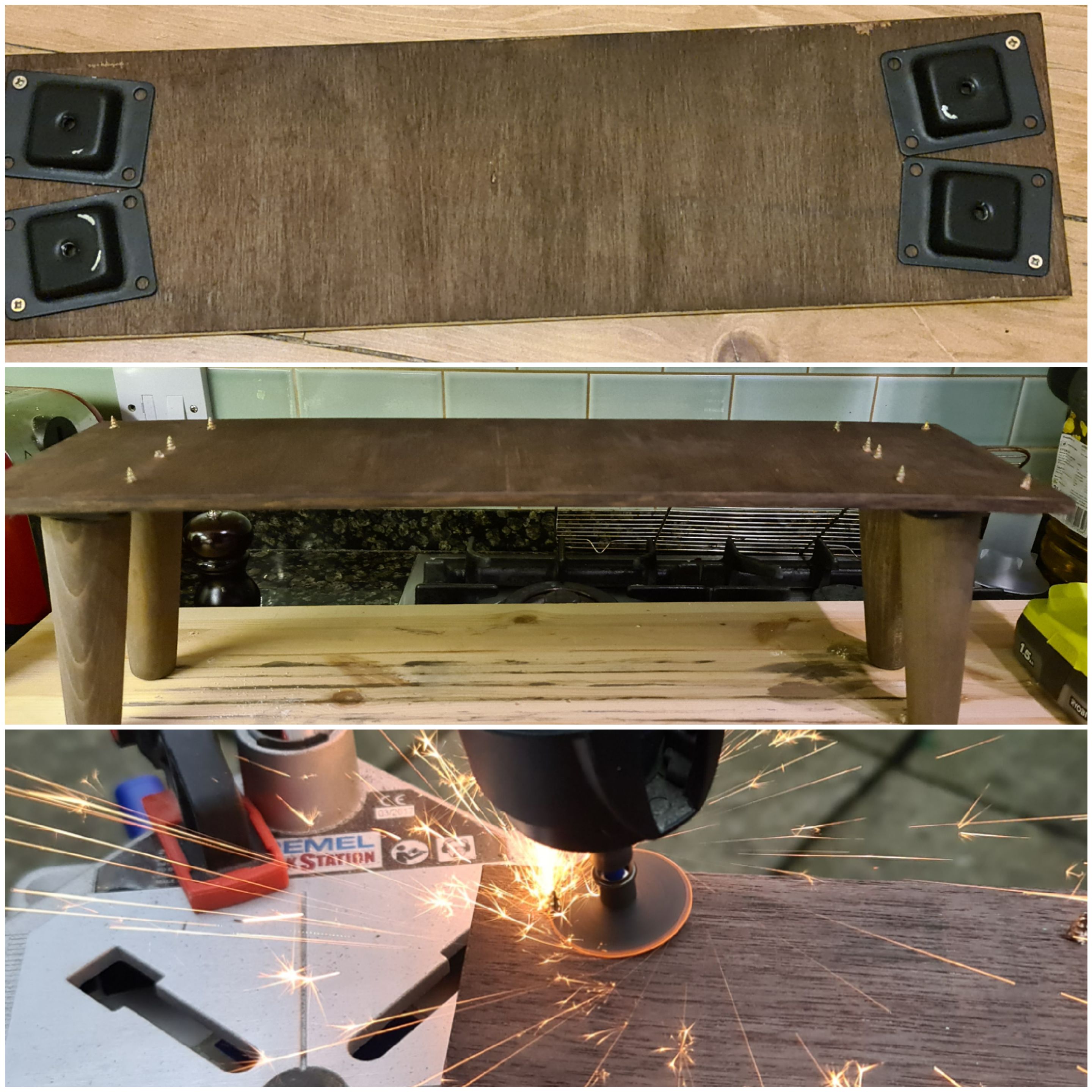
Tapered legs were pretty common for this mid-century era, albeit thinner than those available on eBay. Since the TV may be placed on top of furniture or as a standalone, the legs were attached to a removeable stand.
Another plywood panel was cut and the leg brackets were sprayed black and then screwed in place at a slight outward angle. The screws exceeded the plywood thickness so were cut flush with a dremel and cutting disk.
The legs could then be stained and attached to the board.
Electrics
For portability and ease, a single kettle-lead electrical socket (C14 inlet) was placed in the lower corner of the TV. This was soldered to 3 core cable that then split out to power the TV and a 240v -> 5V 2A transformer (the same as used to power the Raspberry Pi in the smart mirror). The transformer output then went to power three USB devices:
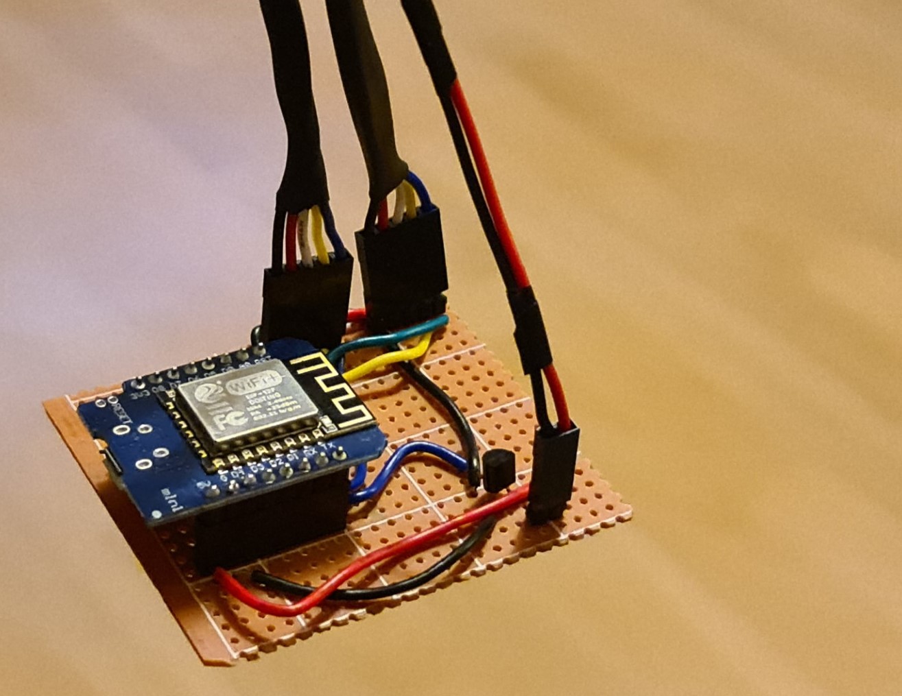
- ESP8266 board - this is the microcontroller to read the volume/power knobs, send IR signals to the TV, and give the system WiFi connectivity
- The Google Chromecast
- An IR repeater - this essentially ‘relocates’ the infrared receiver on the TV (that is now hidden by hardboard) to the back of the TV where it can still pick up instructions from the original remote.
ESP8266 Wiring
The ESP8266 in a Wemos D1 format is what I use in almost all electronic projects as a cheap and basic processor with WiFi connectivity. It can be programmed via the Arduino IDE, making it very easy to interface with a range of peripherals. In the TV it served a primary function of taking a signal from the rotary encoders, and then translating this into the appropriate IR signal as if the remote had sent it to the TV.
The remote control signals were first decoded (using the method described here), which provided the codes for Power, Volume Up and Volume Down:
| Command | Format | Code |
|---|---|---|
| On/OFF | NEC | 20DF10EF |
| Volume UP | NEC | 20DF40BF |
| Volume Down | NEC | 20DFC03F |
This is exactly the same technique as I used in making the Eufy vacuum cleaner smarter.
These codes can then be sent to the TV via an IR LED hooked up to an output pin on the ESP8266. At this point, commands can be sent from the board, or even over WiFi via the MQTT messaging protocol used to control everything on the home automation system running off a Raspberry Pi. However, for now just the signal from the rotary encoders were used to trigger TV commands.
The wiring is summarised in this diagram:
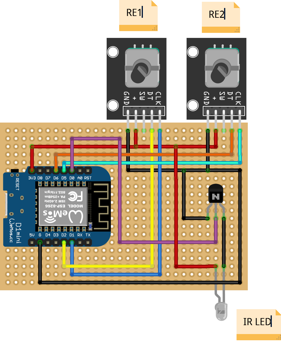
The rotary encoders used are a typical format which offer 3 outputs: CLK, DT, SW. SW is used to read the clicker function (where you can push the encoder in as a click button), and as this wasn’t used it was left unsoldered. The CLK output goes HIGH when the shaft is rotated either way, while DT (direction) goes HIGH or LOW depending on direction. This allows for coding a simple IF statement to calculate which direction the encoder knobs have been turned.
//read Encoder state
nowState1 = digitalRead(CLK1);

//if rotation has moved (a rotary 'click' = high then low sig, so we just read the high)
//Rot1:
if (nowState1 != prevState1 && nowState1 ==1){
  if (digitalRead(DT1) != nowState1){
    Serial.println("Rot1 - CCW rotation");
    //send volume down ####
    irsend.sendNEC(0x20DF40BF,32);
  } else {
    Serial.println("Rot1 - CW rotation");
    irsend.sendNEC(0x20DFC03F,32);
         }
  }
The IR LED is a 940nm wavelength (a useful trick is using a phone camera to see if it’s flashing, as it’s invisible to the human eye) and as it pulls slightly higher current than the ESP8266 pins can provide, an NPN2222 transistor is used as the electrical ‘switch’ to complete the LED’s circuit while keeping the ESP8266 pin electrically isolated. The LED was ultimately placed right up against the corner of the TV from behind, as close to the TV’s inbuilt receiver as possible inside the box.
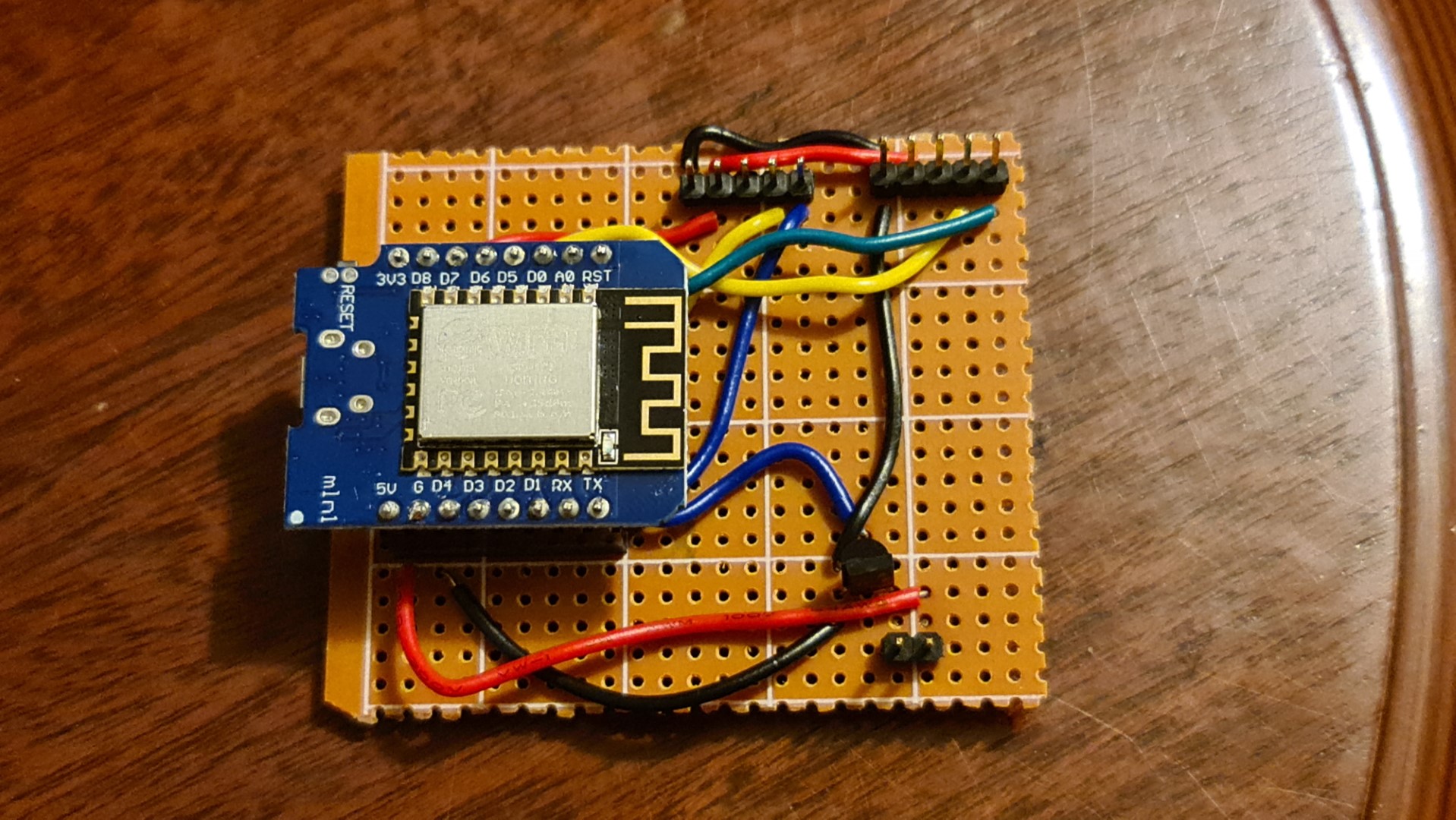
To keep things modular for ease of assembly and in case parts needed swapping out, the wiring was soldered with header pins rather than wiring all the components permanently to the board.
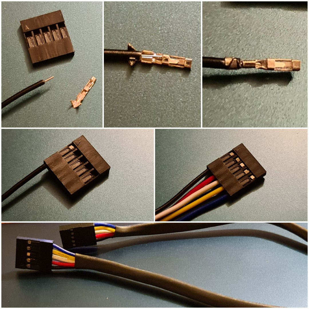
To connect to the encoders and IR LED, dupont cables were made with single core wire and a set of crimp connectors, a new skill acquired for this project, but extremely useful for future projects. The wire creating process is illustrated here:
So when fully connected, the circuit looks like this:
The final code for the ESP8266 is located here, and includes all the functionality for taking IR commands over MQTT as well as OTA (over the air) firmware updates so the ESP doesn’t have to be directly plugged in if something needs to be changed in the code.
Final Assembly
For the backing, a simple piece of 3mm plywood was cut to shape with gaps for the IR repeater receiver and the power supply. Vents were also cut at the top which roughly line up with the existing vents on the TV itself, as backlights in these devices can get hot over time.
Instead of hinges, neodymium magnets were glued into the corners/edges for a simple click-on backing that can easily be removed if something needs to be changed. Four magnets provides plenty of holding power for the board, and standard cyanoacrylate glue provided a strong enough bond to the wood.
*Click to see magnetic closing*

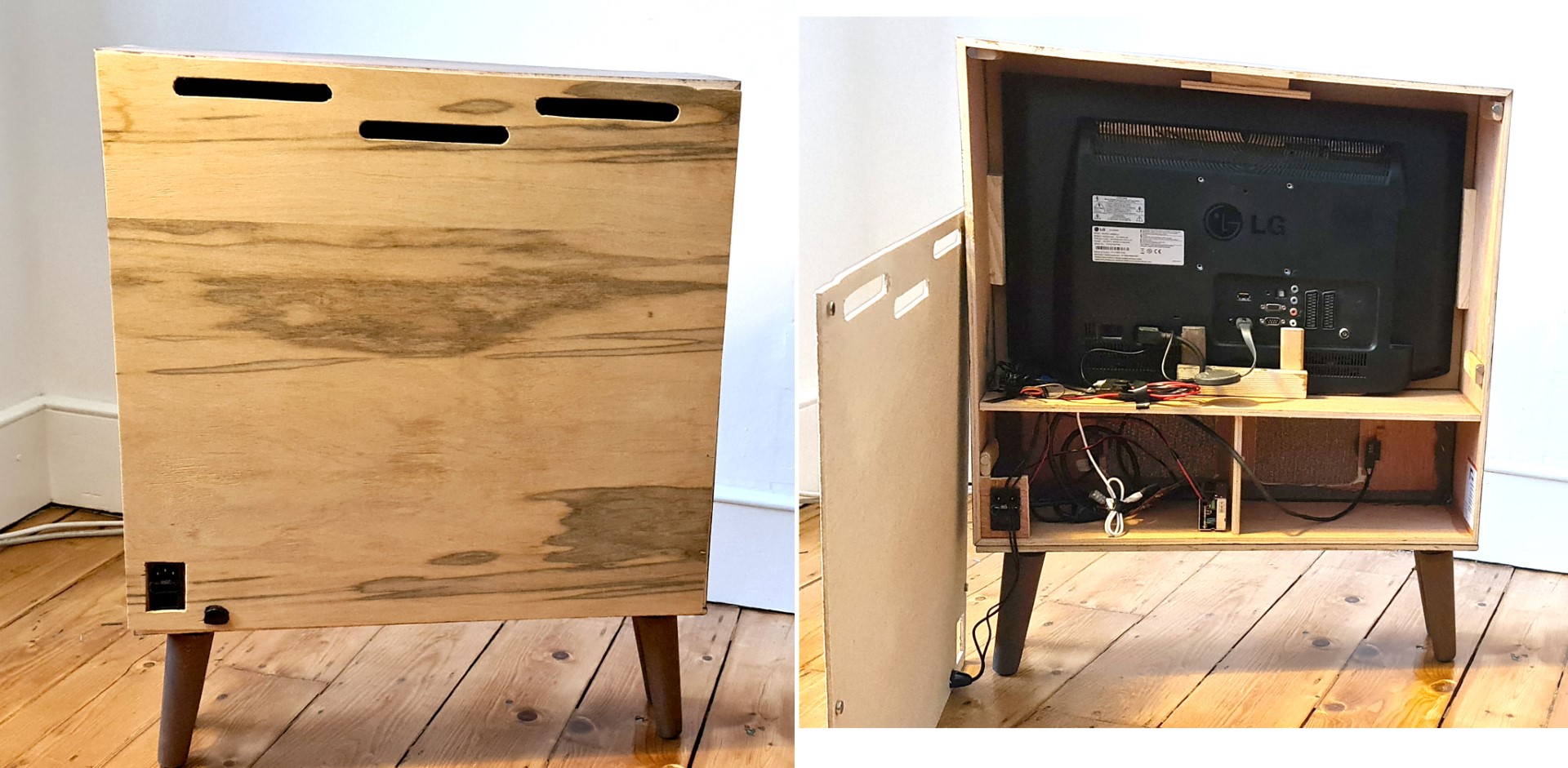
The backing both on and off the final build
Despite polling the rotary encoders only at the speed of the ESP8266 loops, the knobs translate to volume controls smoothly, with minimal delay and function as desired, as seen in this clip below:
*Click to see rotary dial function*
Volume Control:

Power Control:
Closing
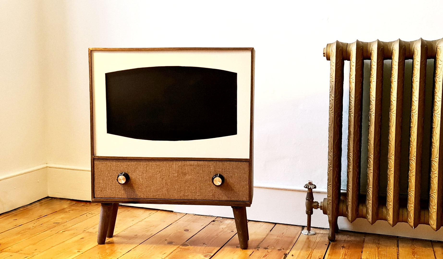
The final result came out pretty well, and with the inbuilt Chromecast, it’s simple to stream content from phones/laptops, limiting TV functionality. The IR repeater also allows the original remote to function too. So it’s basically a wooden box for a TV. Maybe it looks a bit better than black plastic on the wall.