Raspberry Pi 4 Home Server
I decided to build a dedicated enclosure for the raspi running my home server.
I started with a bare board and graduated to a cheap enclosure with an inbuilt fan from eBay. This worked fine, but once I added an external hard drive for networked attached storage (NAS), I decided to make something a little more robust.
I started with what was described as a .50 cal ammunition box off Amazon, as seemed to fit the dimensions of my 3.5” HDD dock along with the extra length for the Pi and power splitter.
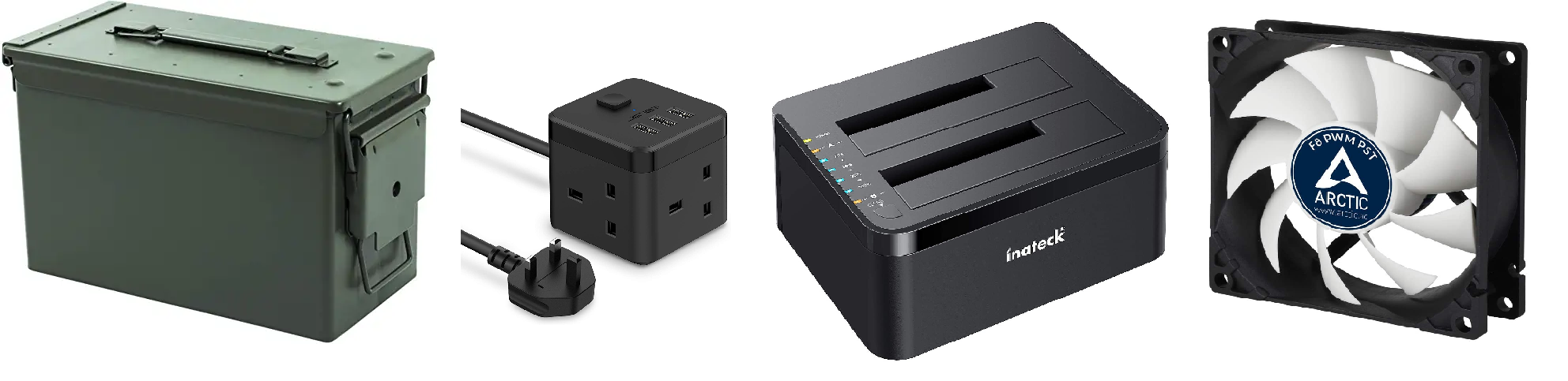
I also wanted to keep it cool and in a waterproof metal box, this seemed unlikely. So I added the cheapest PC fans I could find in a slim, 80mm format.
Finally, I decided not to strip and combine the mains powerlines (mainly so that if it all failed, I could reuse all the components) and bought the smallest 1 to 3 extension lead I could find, which had a neat cube-like form factor.
Once the parts arrived, I realised I wrongly measured and had to cut the end off my twin slot HDD bay dock. I unscrewed the base to check the PCB was well out of the way and then chopped off the end with a hacksaw.
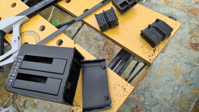
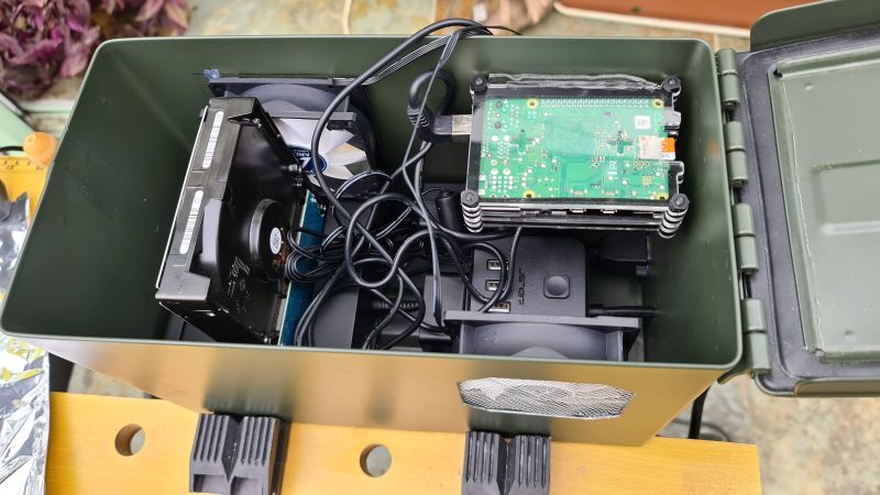
I then laid out the parts to work out where everything would go, before clamping the box in a workbench to make holes.
I started with marking out where the fans would go - I wanted the intake somewhere near the Pi, and the exhaust by the warm disk drive. I couldn’t do them at the short ends as the HDD pretty much completely blocked all air flow, so they’re on the sides and I figured offsetting them would prevent air flow just going straight through and not wandering around the components.
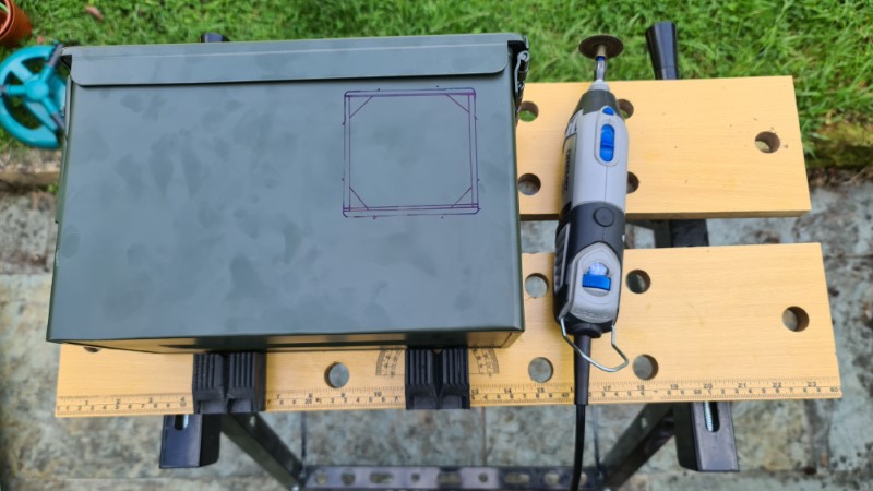
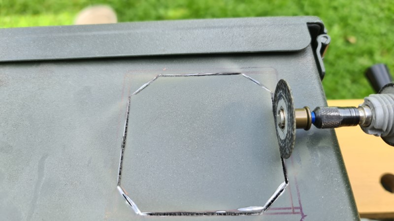
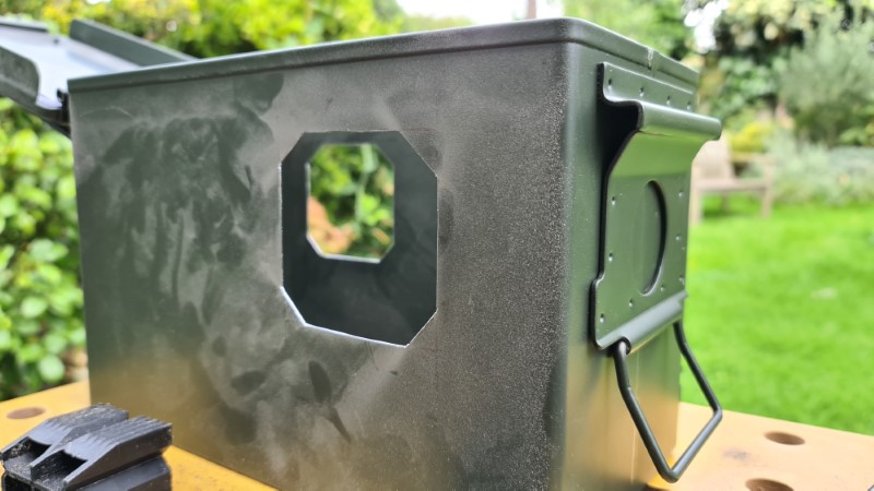
A dremel with a cutting disk made easy work of the thin metal and with some filing, I had decent ‘non-jagged’ holes.
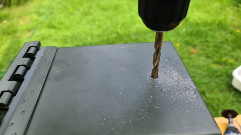
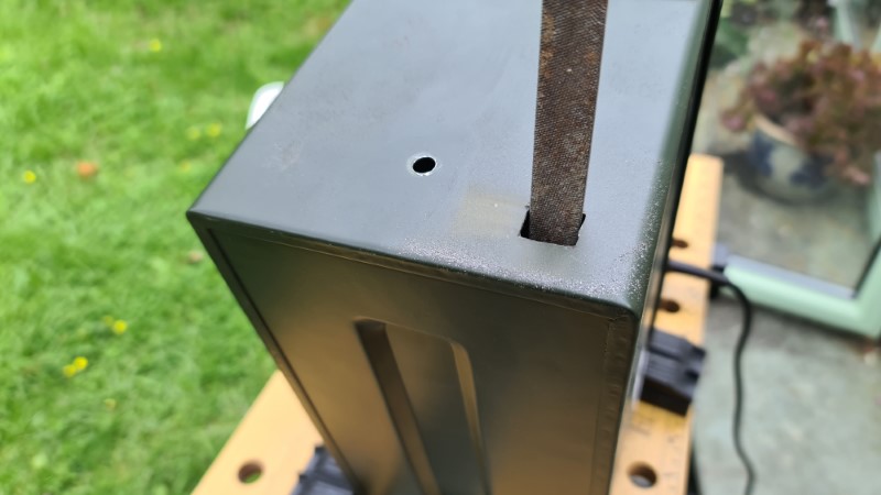
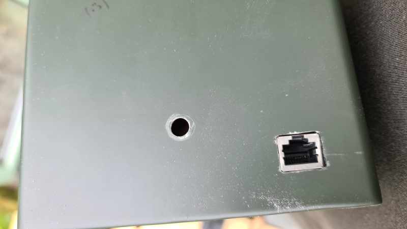
I checked the height of the power cable on the extension lead and drilled the appropriate 7mm hole (figuring out I had to drill many prior holes, gradually increasing bit diameter to work up to 7mm).
The ethernet port at the back needed to start with a round hole (couldn’t get the dremel to cut so small) which I then filed out to be square. I used a 30cm ethernet extension cable allow this socket to be distant from the Pi.
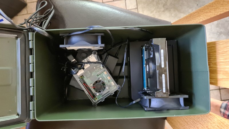
Then was a simple task of hot-gluing all the components in. I quite like hot glue as on smooth surfaces like this, it’s easy to sort of ‘snap-remove’ things if you make a mistake.
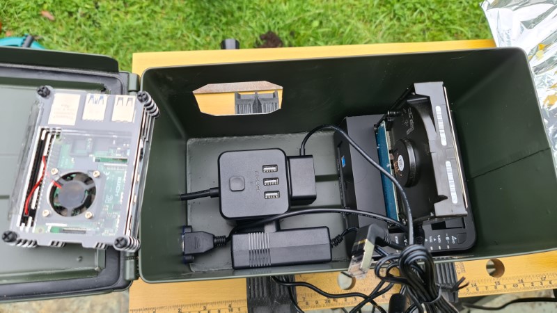
I glued some metal mesh over the intake fan to prevent things (dust, wires, fingers) being sucked into blades (although still managed to cut myself on one of them somehow).

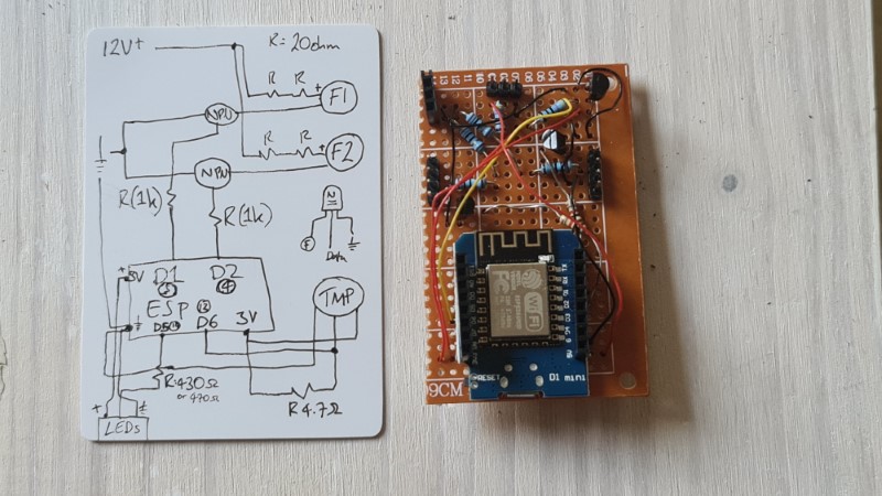
Once all in place, I needed to build something that would control the fans. I only wanted them on when the Pi CPU was running hot, so I decided to build a controller with an ESP8266 (Wemos D1 - a wifi-enabled microcontroller). As the fans ran off 12V, which I had from the HDD dock, I used NPN transistors as the electronic ‘switches’ for the ESP’s 3.3V board logic. I also wanted some LEDs inside, so made a wiring plan for the two fans, the LED strip and a temperature sensor (DS18B20, my favourite digital TMP sensor).
The fans were actually way too loud at 12V, so I added the appropriate resistors to bring them down to 8V which was much quieter while still kicking out a decent flow rate. These fans could actually be controlled via PWM, but I discovered the ESP8266 can’t generate a high enough frequency, so had to give up on that.
I used header pins as ‘sockets’ for the LEDs and fans as soldering everything at that point would be very messy and constrained.
Once wired and soldered on some prototype board, the controller was ready to be incorporated. Neatly, the extension lead had USB ports (rated up to 2.1A, which was needed for the LEDs) so I could power the ESP8266 directly without an extra power supply.
The LED strip uses the WS2812 controller with 5050 RGB LEDs. What does this mean? It means each LED is individually addressable, so you can do some fun things with the leds whereby any one can be any colour. I mainly wanted this so I could light different parts of the enclosure in different colours.
**Expand to see LEDs**

Finally, I flashed my Arduino code (code) to the ESP8266 fan controller. I could have hardcoded it to automatically start the fans when the temperature sensor onboard went above a certain level, but decided instead to control it via the home automation server actually running on the Pi.
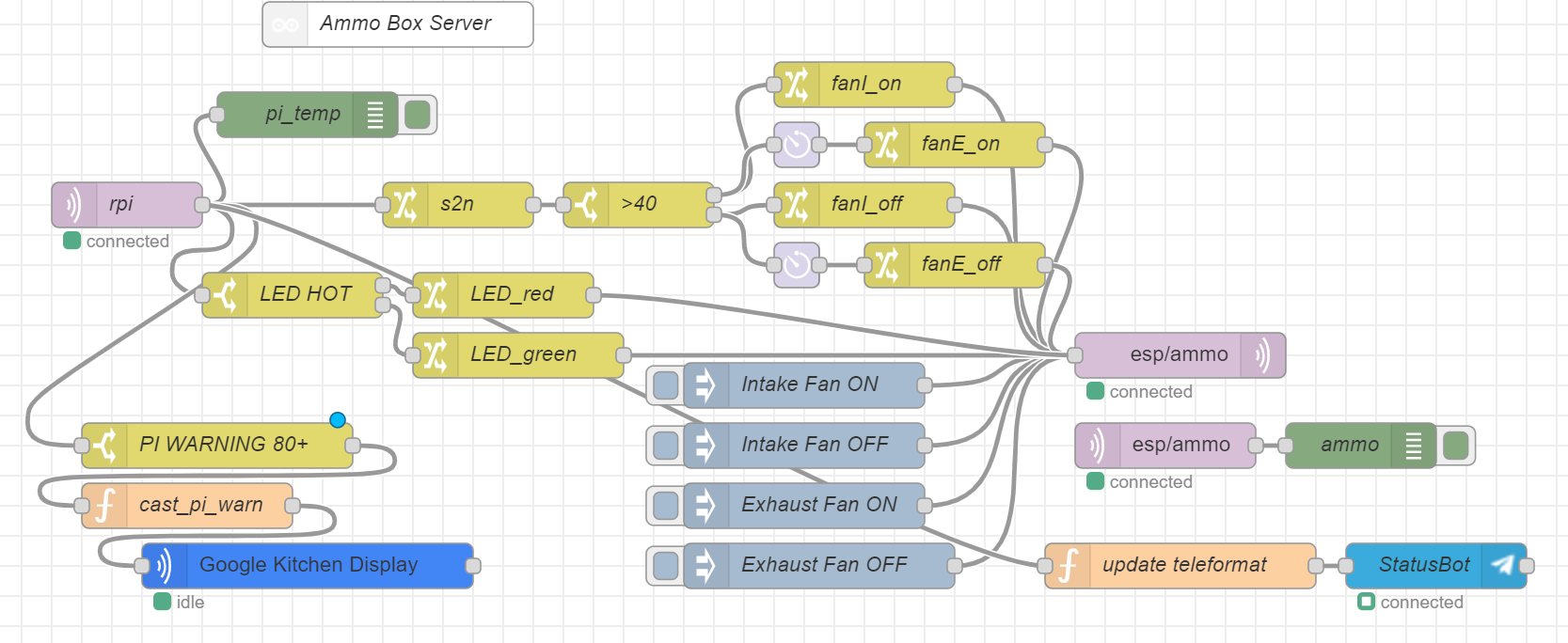
The flow is therefore:
- Raspi CPU Temp published to Node Red every minute
- Node Red uses a switch node to determine if CPU temperature is above 50C
- If hot, a message is sent via MQTT back to the ESP8266 to turn the fans on
- If the temperature exceeds 80C, the LEDs go red and Node Red streams an announcement to google home to warn me the Pi is overheating
And that was it, took a couple of hours and the Pi was ready to sit in a cupboard somewhere to continue running all its dockerised functions.
If I were to do it again, I’d probably pick quieter fans, and I would wire in a power socket, rather than a permanent 1m black cable coming out the back of it.