Reducing Repetition - my first PCB
A custom PCB, a printed circuit board, is surprisingly sraightforward to obtain.
As my home automation network slowly grows, I started to find building similar nodes for each room quite repetitive. By node, I mean one Wifi-enabled unit consisting of a microprocessor (all ESP8266s in this case) and an array of sensors.
Some of these are unique, like the power meter for measuring energy usage or a particulate matter sensor for air quality; but the most basic unit will always be temperature and motion. Temperature is just a very easy and somewhat useful measurement to start with while motion detection will always be a cornerstone of automation projects. By running the MQTT messaging server, allowing each node to send and receive messages across the network, it doesn’t matter which device detects motion and which one controls the outcome (e.g. lights, blinds, music, etc.) - so if there’s a motion sensor in each room, you have a good basis for any future automation.
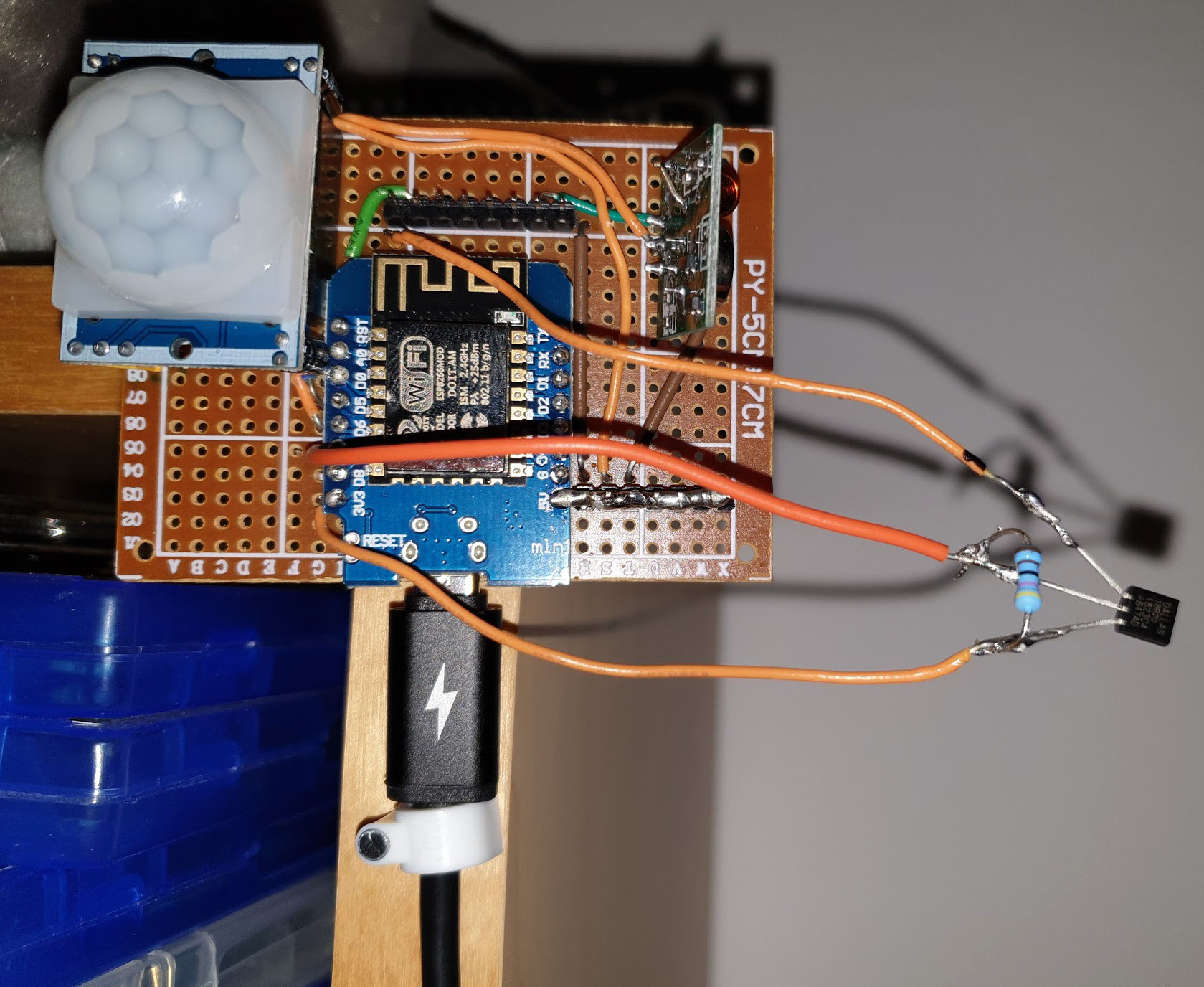
My recent ‘nodes’ were constructed of prototype boards, 30AWG wire and lots of solder.
As I was always adding the same initial sensors, I followed the excellent sparkfun tutorial here to download Eagle (free software) and started playing with PCB design.
I wanted something that would take the ESP8266 in its Wemos D1 format, a PIR motion sensor, an OLED display and a temperature sensor (or two as they can be polled in serial off one pin). I played around with an LED and an extra 3.3V and 5V placement too for extra sensor addition.
PCB design
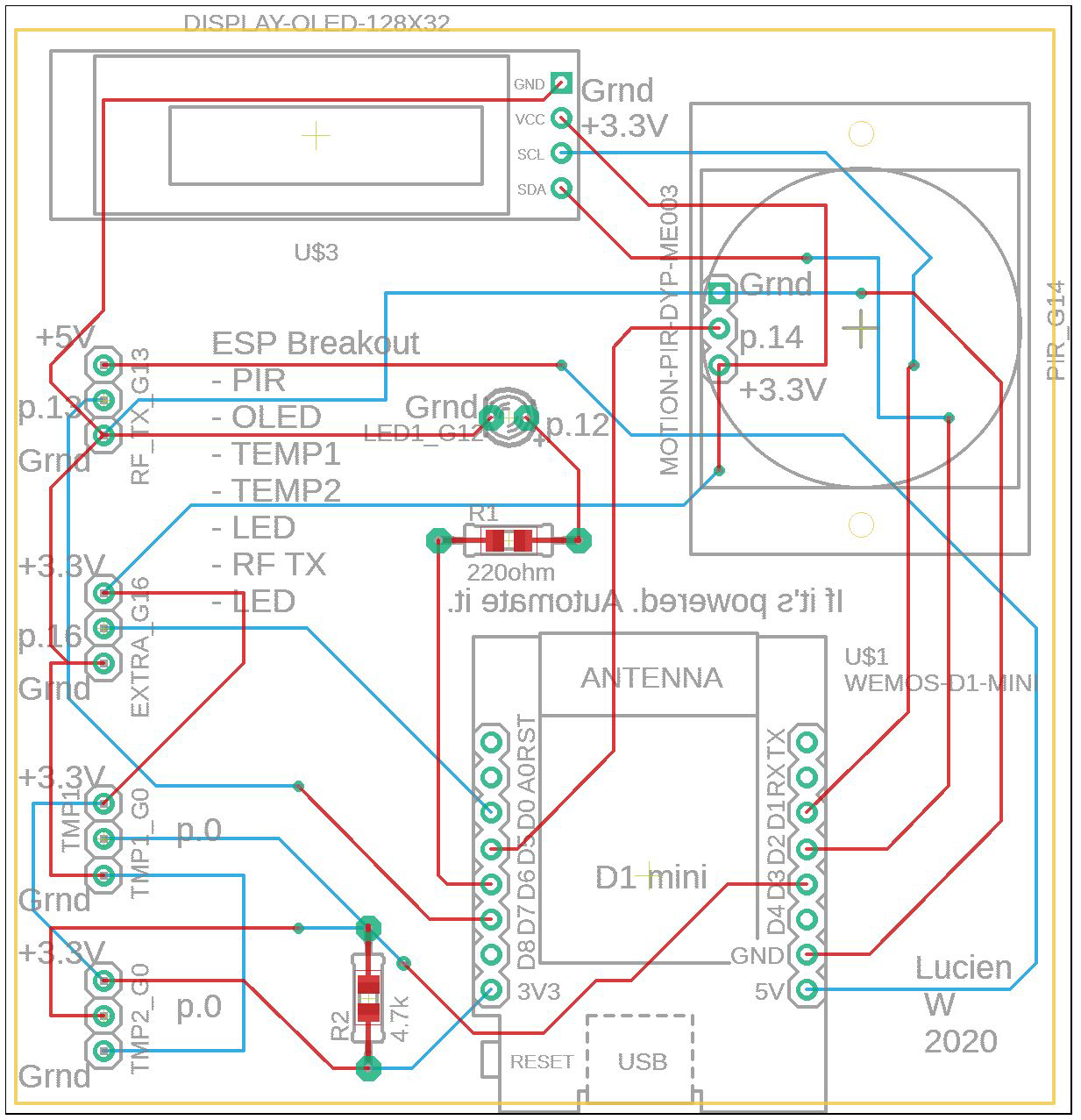
I started with a schematic with all the main connections:
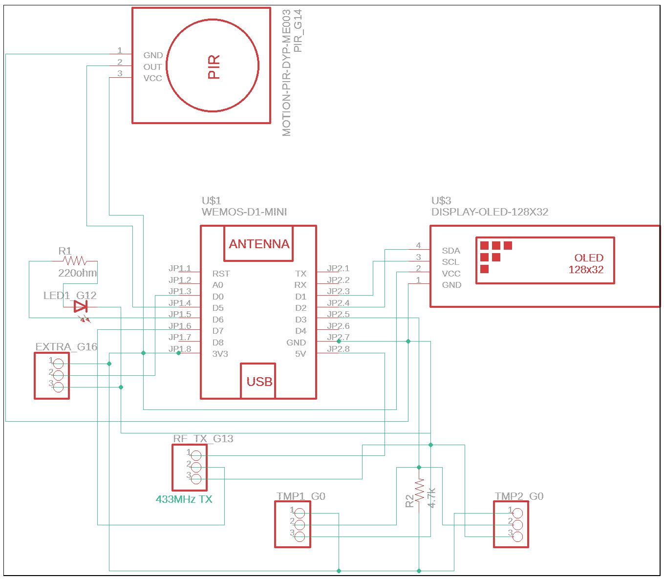
And then played the fun, problem-solving game of mapping the schematic out onto silicon:
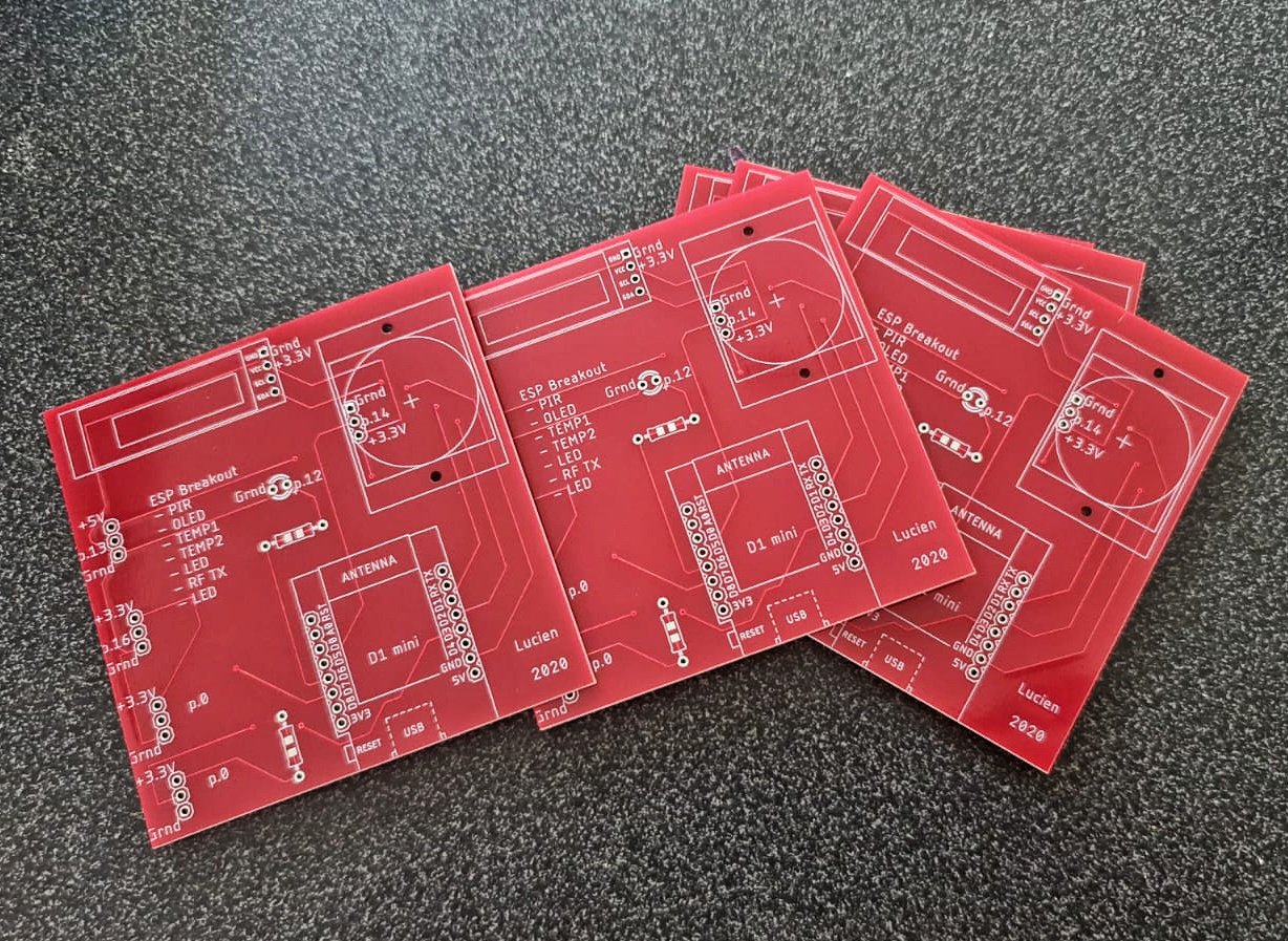
Once done, I selected a company that makes PCBs for a reasonable price (given this was my first attempt and I didn’t want many). Elecrow was the best value for me and I ordered 10 boards for about a dollar each.
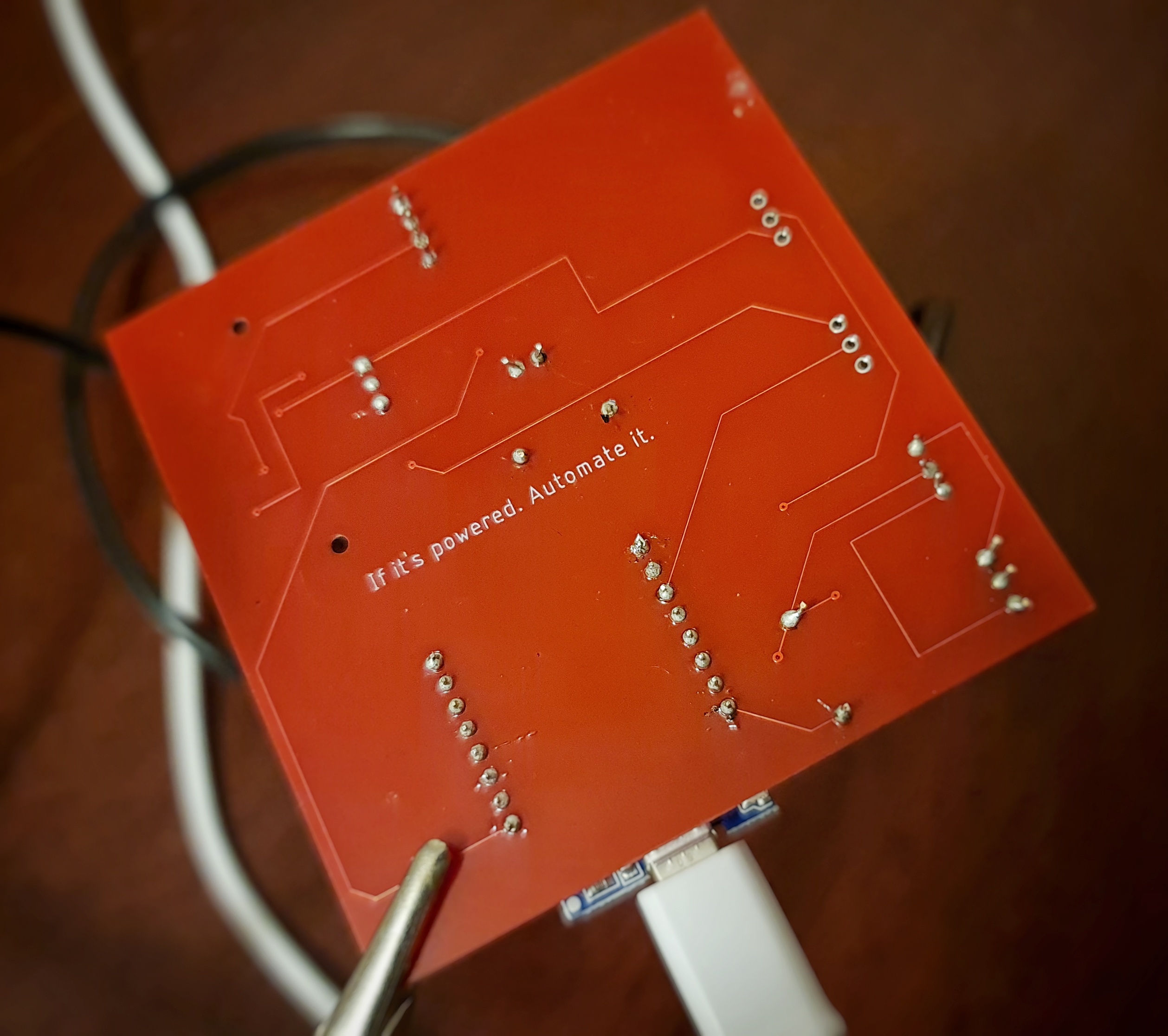
About a month later, they arrived:
Components
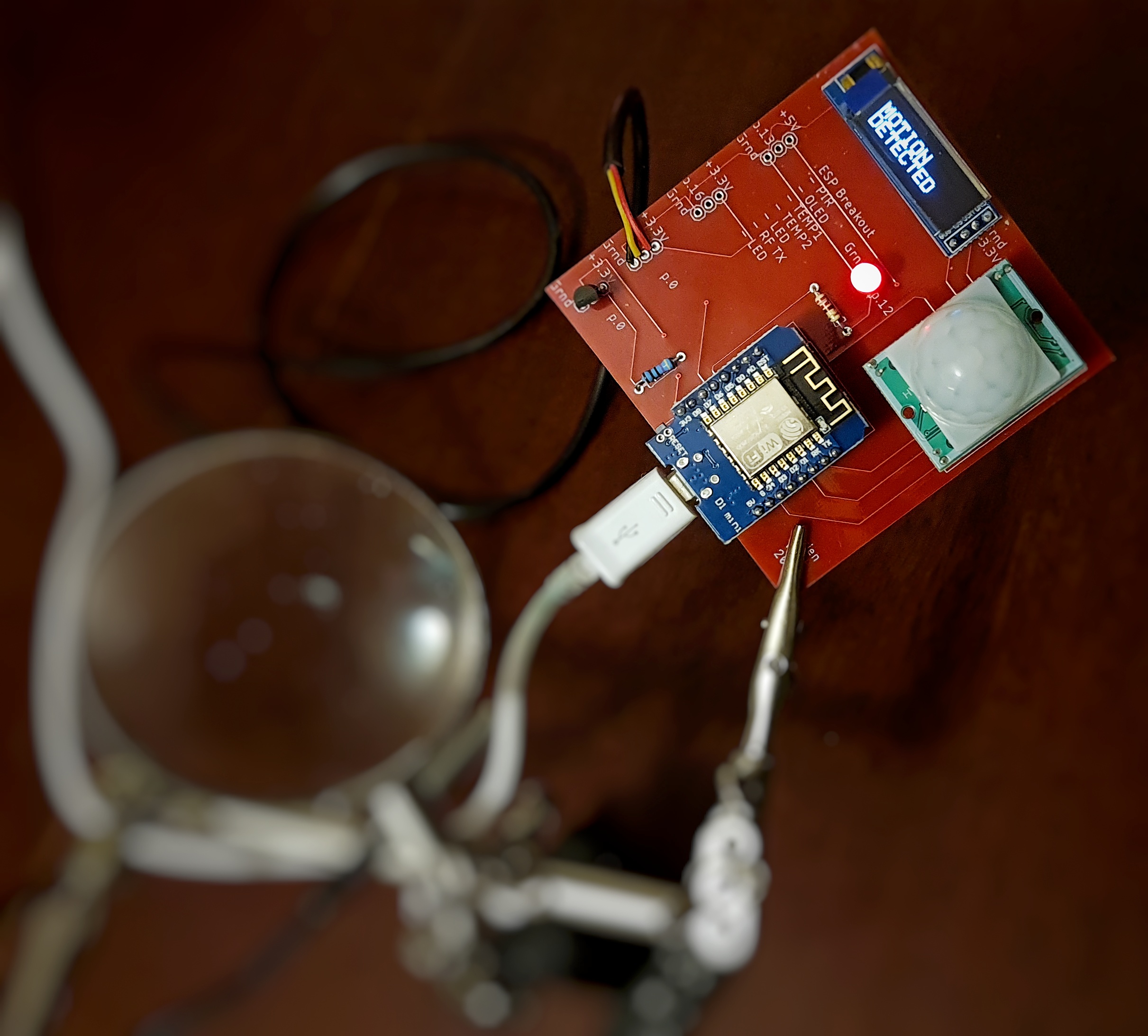
I soldered the parts I wanted and uploaded a basic code to read the temperature sensors (2x DS18B20s, one on the board and one on a probe for external measurement), read the PIR motion sensor, and light the LED up for motion while displaying the temperature values on the little 32x128 OLED display.
(For actual home automation and not just a local sensor, this would also include all the Wifi and MQTT pubsub code too).
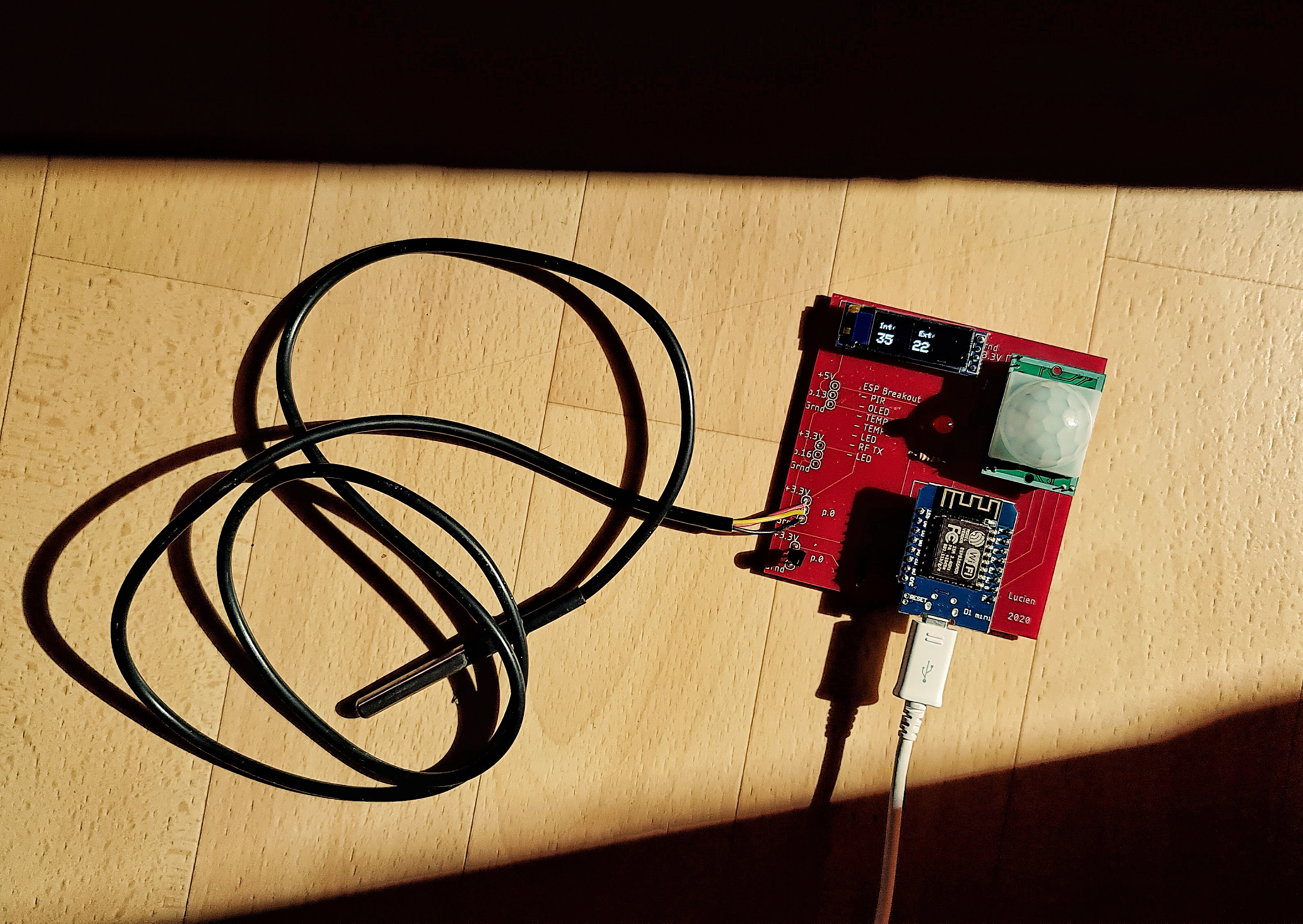
You can see the code in action here:
PCB gif
Closing
This was surprisingly easy to get a working PCB for repetitive tasks. I’m not saying it’s expertly designed on any level (or I’ll even end up using) - the thing is huge, and the ‘extra sockets’ I left are a little too rigid in their assumptions other sensors would have a ‘ground-signal-power’ format. Which any of the useful ones I wanted to add didn’t (RF transmitter/receiver, hall sensor, anything needing a transistor).
But the next time I settle on a design that I’ll be wiring repetitively, PCBs are definitely the best use of time and money.